The following is taken from the Royal Navy's Torpedo Drill Book, 1914 (corrected to May 15), published by His Majesty's Stationary Office. The Torpedo Department, besides being responsible for the torpedoes themselves, were the men responsible for all electrical fittings in British warships: the information below describes the gunnery fire control mechanisms, but from the view point of the electricians who looked after their maintenance, and not the gunners who used them.
All ships are now fitted with some system for controlling the fire of the guns.
There are usually two controlling positions aloft and two transmitting stations below, where the instruments to indicate the range, deflection and orders at the guns themselves are placed. The transmitting instruments are below behind armour and there is communication to them from the control positions aloft by voice pipe, navyphone, &c.
All later ships have three or four control positions.
The grouping of the guns varies in the different classes of ship, but a group or change-over switch is usually fitted below, to allow the various groups to be controlled from either or both transmitting stations.
A single-stroke gong is fitted at each gun, close to the gunlayer. It is used when giving the signal to fire when salvo firing is employed. These gongs are operated by pushes in the transmitting stations and control positions.
A loud sounding trembler bell is fitted in each transmitting station and at each gun, and all the bells are operated simultaneously by a push in the conning tower. This is for the captain to order "cease fire" at any time or to call attention to the fact that some important order is being passed.
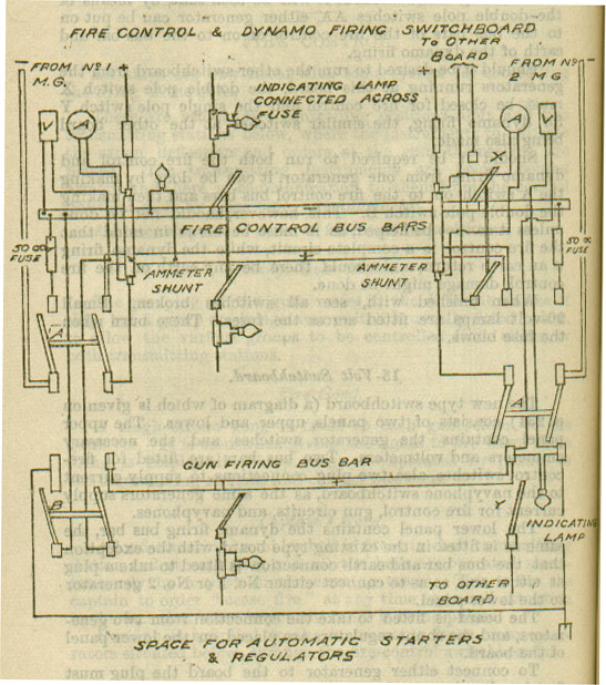
Current is supplied to the instruments from motor-generators situated below, through the fire-control switchboards.
There is usually one switchboard forward and one aft, the switchboards also being used for dynamo firing, the upper part of each being for fire control and the lower part for dynamo firing. There are four motor-generators, two to each switchboard.
Referring to the woodcut it will be seen that, by means of the double pole switches AA, either generator can be put on to the bus bars of the fire control or on to the bus bar and earth of the dynamo firing.
Should it be desired to run the other switchboard from the generators running at this board, the double pole switch X must be closed for fire control and the single pole switch Y for dynamo firing, the similar switches at the other board being also made.
Should it be required to run both the fire control and dynamo firing from one generator, it can be done by making the A switch on to the fire control bus bars and then making the double pole switch B. This, however, should not be done unless it cannot be helped, as it must be borne in mind that the fire control is a complete circuit, while the dynamo firing is an earth return, and should there be any earth on the fire control, damage might be done.
When finished with, see all switches broken. Small 20-volt lamps are fitted across the fuses. These burn when the fuse blows.
The new type switchboard consists of two panels, upper and lower. The upper panel contains the generator switches and the necessary ammeters and voltmeters. Two bus bars are fitted for firecontrol switches, also two plug connections to supply current to the navyphone switchboard, as the same generators supply current for fire control, gun circuits, and navyphones.
The lower panel contains the dynamo firing bus bar, the same as is fitted in the existing type board, with the exception that the bus bar and earth connection is fitted to take a plug at either end, so as to connect either No. 1 or No. 2 generator to the lower panel.
The board is fitted to take the connection from two generators, and the shunt regulators are placed on the lower panel of the board.
To connect either generator to the board the plug must first be placed on to the generator switch connection and also on to the bus bars. The plugs connecting the positive and negative leads are different in size, also the holes into which they fit, so as to prevent mistakes in joining up.
The boards can be parallelled in the usual way by means of double and single pole switches.
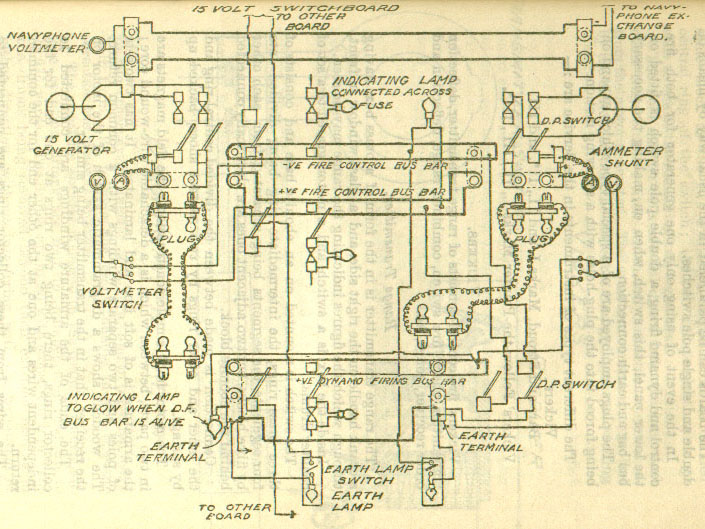
In the event of using only one generator for both fire control and dynamo firing, a double pole witch is fitted on the lower panel, this switch, when on, making the necessary bus bar and earth connection.
The plugs employed are of a special type which expand on being forced into the plug-holes with a screwing motion.
The different types of instruments in the Service are:-
Vickers',
Barr and Stroud, Marks I and II., II*, and III.
Vickers' Follow-the-Pointer Marks I, II, III, III*.
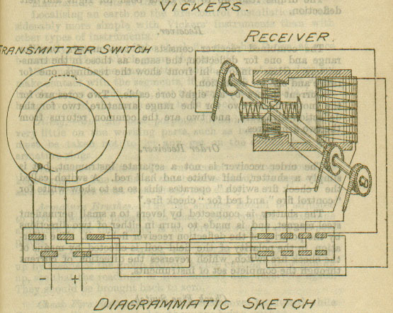
Vickers' fire-control consists of range transmitter, deflection transmitter, check fire switch, combined range, deflection and order receiver, gongs, &c.
The range transmitter is in the form of a brass box, having a crank handle on the right side, and a glass window in front, through which the figures indicating the range may be seen.
Inside the box is a switch, and a motor, geared to a set of counter drums.
The switch is mounted on an ebonite base and consists of three brass rings, the intermediate ring being divided into four segments, the segments being separated from each other by fibre blocks, but two adjacent ones are electrically connected behind the ebonite block.
Connection is made between the divided central ring and the inner and outer rings by two contact shoes, backup up by springs.
The motor is of simple construction; the field magnets are in two parts, between which is a detachable wire-wound core; the armature is of soft iron and laminated. It has two sets of poles and two separate windings with a common return. The woodcut shows a diagrammatic sketch of the motor on the receiver, that in the transmitter being similar.
The ends of the armature windings are connected to collector rings, there being two rings at one end for the independent wires and one at the other end for the common return.
The wires from these collector rings are connected to terminals on a terminal plate, the common return wire to the same block as the two connected segments of the divided central ring of the switch; the two independent wires go each to one at the remaining two segments.
The field magnet coils are fed direct from the inner and outer rings of the switch which are connected to + and -from the motor generator. The armature current is controlled by the switch, so that the current is changed from one winding to the other every quarter of a turn, and in direction every half turn. By turning the crank handle in the opposite direction the motor is reversed.
The armature spindle is geared to the counter drum shaft. The counting drums are four in number and read up to 19,975 yards. The drums are fitted with stops, which prevent the drums being revolved beyond their extreme reading in either direction, without interfering with the revolution of the armature. This affords a means of bringing all receivers to the same reading should any of them have got out of step.
The deflection transmitter is similar in construction to the range transmitter, the only difference being that the counting mechanism has two independent pairs of drums, one for right and one for left deflection. Each drum is provided with a shutter so arranged as to fall over the deflection not in use.
The drums read up to 50 knots both for right and left deflection.
The combined receiver consists of two motors, one for range and one for deflection, the same as those in the transmitters. Glass windows in front show the readings, one for range and one for deflection.
Current enters by an eight-core cable. Two cores are for the motor fields, two for the range armature, two for the deflection armature, and two are the common returns from the two armatures.
The order receiver is not a separate instrument, but is simply a shutter, half white and half red. A switch called the "check fire switch" operates this so as to show white for "control fire" and red for "check fire".
The shutter is connected by levers to a small permanent steel magnet, and is made to turn in either of two directions by the polarity of the deflection receiver field coil. The alteration in the polarity of the field coil is effected by means of the check fire switch, which reverses the direction of current through the complete set of instruments.
A check fire switch is provided for each group of guns, and is so arranged that the mains pass through it before entering the instruments at the transmitting station.
It should not be worked until the transmitters are at rest, otherwise the receivers will probably get out of step.
The fire gong is of the single stroke type and is operated by the fire gong key.
The captain's bell is a specially wound trembler bell with a distinct tone. One key in the conning tower operates all the bells simultaneously.
Maintain 20 volts at the fire control switchboard.
Localising an earth on the fire-control installation is considerably more simple with Vickers' instruments than with other types of instruments.
Firstly, by means of the check fire switches it can at once be ascertained on which group the earth is.
Secondly, as the transmitter switch, when at rest, does not make contact with the segments, if the earth is present when the check fire switch is on, but the transmitter handle is not being revolved, the earth must be in a field coil.
Oiling.-Use the pest porpoise oil, and occasionally put a very little on the working parts, such as bearings; but care must be taken not to let any get on the switch face and armature rings.
Transmitter Switch.-The surface of the rings should be kept bright. The ends of the brushes should be kept clean, and the brushes must work freely and easily.
Armature Brushes.-The flat springs should be adjusted to give sufficient pressure to make good contact. Examine armature to see that there is not dirt between it and the pole pieces.
Separate Control.-When the control of the guns is split up by means of the group switch, before cutting out or joining up, see that the readings of transmitters and receivers agree. They should be brought back to zero.
Check Fire Switches.- These should never be altered while the transmitter connected to them are being worked.
Working the Transmitters.-do not work them too fast. When finished with, and before leaving the transmitters, the range drums should be brought to zero, and a few more turns given to the handles. Also the deflection drums should be run up either right or left as far as they will go, a few more turns given, and then brought back to zero. This is to enable all the receivers to be adjusted in case any are out of step.
Mechanical Gear for Resetting Receiver Drums.-Due to the time taken to get Vickers' instruments into step by the method already described, the following mechanical method has been adopted:- Holes are drilled in the side of the combined receivers to allow a key to take over the spindle of the dial drums; by this means the drums can be quickly reset. The holes are threaded and a nut with a washer can be screwed in to keep the case watertight when the key is not in use. In using this method care must be taken that current is first switched off by the "check fire" switch.
These instruments are obsolete and will not be described here.
The instruments consist of:-
(1) Combined range, deflection and order transmitter,
(2) Combined range, deflection and order receiver,
with the usual gongs, &c.
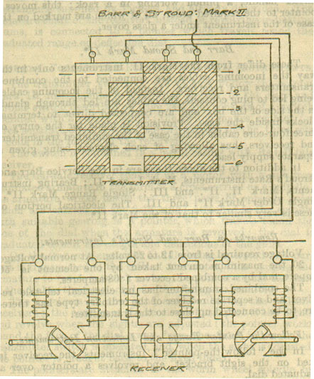
The receivers, range, order, or deflection, each consist of three electro-magnets placed side by side, and a shaft with three soft iron armatures 120º apart placed between the poles of the magnets. It is possible to energise one magnet at a time or two magnets at a time. In this way six position are obtained in 180º of turning of the shaft.
The transmitter switch consists of a glass cylinder on which is a German silver contact strip. In the woodcut it is shown opened out flat. Bearing on this cylinder are four spring fingers. The cylinder is revolved by a handle and so energised the magnets of the receiver in turn, giving the six positions referred to.
There is one feed to the transmitter, which is always on to "contact," and one feed to the receivers, which is common to all three magnets. One feed is sufficient for range, order and deflection, so the number of wires required for one set of instruments is:-
1 feed to transmitters
1 feed to receivers
3 line wires range
3 line wires deflection
3 line wires orders
On the receiver shaft is a toothed wheel, which gears into the drum, showing the 25 yard intervals; this drum works the 100 and 1,000 drum with ordinary gearing.
The range transmitter handle is provided with two speeds; to shift from one to the other, place the handle in a horizontal position and force it in, when it engages in a smaller gear wheel. When geared for fast speed, one complete turn of the handle registers 100 yards and when for slow speed 25 yards.
The mechanical arrangements of the deflection receiver is as follows: There are two drums, one inside the other; the inner one has two rows of numbers (1 to 10) marked round it, one row marked forward, the other backward; these numbers in turn show through a hole cut in the outer drum which has the word "left" (or "right") in line with the hole; when the inner drum has revolved one complete turn, and goes from 9 to 0, a stud turns the outer drum one position when left (or right) 1 will be in line with the hole through which the unit number is showing.
The "orders" are visible at the transmitter. This is allowed for mechanically by gearing on to the order transmitter handle, a pinion working in a rack; this move a pointer to the required order, all of which are marked on the case of the instrument under a glass cover.
These differ from the Mark II instruments only in the way the incoming cables are connected to the combined transmitters and receivers. Instead of the incoming cables being led to plug contacts, the cables are led through glands in the side of the box and are connected direct to terminal blocks inside the case. Provision is made for the entry of three four-core cables in the case of the combined transmitters and receives, thus allowing of each element being given a separate supply lead.
In addition to the above there are in the Service Barr and Stroud's Rate instruments, Marks I and II; Bearing instruments, Mark II, II* and III; Single Range, Mark II*; Single Order Mark II* and III. The electrical portion of these is very similar to that of the Mark II.
Voltage required is from 12 to 25 volts. At normal voltage of 20, the maximum current taken by one element is .56 ampere, and by a combined receiver 1.68 amperes.
The combined transmitter has no electrical tell-tale receiver, and a separate receiver of the ordinary type has, therefore, to be connected up close to the transmitter.
In the "follow-the-pointer" instruments the receiver is fixed on the sight bracket, and revolves a pointer over a graduated dial.
The sights are set in the usual manner by revolving a wheel by hand, but, in addition to raising or lowering the sights, this hand-wheel also revolves the graduated dial, so that the sights can be set by keeping the pointer opposite to a zero mark on the sight bracket, as the pointer is worked by the receiver.
The range and deflection instruments are separate by similar in design electrically. The transmitter contain their own electrical tell-tales. Order instruments of the Barr and Stroud type are used with this system, but none are fitted in second and third class cruisers.
Mark I Instruments are similar electrically to the dial instruments supplied by Vickers and already described. The armature shaft of the receivers, instead of revolving indicating drums, is connected to a pointer which travels round the graduated range or deflection dial.
The transmitter switch of the Vickers' Follow-the-pointer Mark II instruments is somewhat similar to the Barr and Stroud switch described, and consists of a switch operated with a rotary handle; the switch makes contact for three separate circuits which supply current to the three sets of coils in the motors of the receivers.
The switch is contained in a metal casing with its tell-tale receiver.
The tell-tale receiver consists of a motor with a soft iron laminated armature in the form of a cross carried on a spindle, the armature works inside the three pairs of opposite poles which are carried on the field ring; attached to the spindle with suitable gearing is a pointer, which travels round the face of the dial when the armature is revolved; the dial is graduated to suit the ranges and deflections of the guns.
On the transmitter switch handle being operated the current is transmitted to the coils of the motor, thus causing the armature to revolve, which moves the pointer round the face of the dial to the range or deflection being transmitted.
The receivers at the guns are similar to the tell-tale receivers; the casing of the receives form part of the sights and revolve when the sights are adjusted; the pointer works round the face of the dial away from the fixed index as the transmitter switch is operated, and, when the sight is adjusted, the pointer is brought back to the fixed index.
The pointers are attached to the worm wheel spindle by winged nuts, and can be clamped in any position.
Should the position of the pointers of the receives be altered, it is necessary, in order to reset the pointer, to have the current on the circuit and to revolve the transmitter switch until its tell-tale receiver pointer is at zero; the pointers at the guns should then be reset by easing the winged nut and setting the pointers at zero.
These are very similar to the Mark II instruments, the principal differences being that the transmitter switches are in separate casings to their tell-tale receivers, and the casings of the receivers on the sights form part of the sight, the electrical portion being attached to a base plate which is secured to the casings by means of screws.
Improvements have been made in the method of winding the field coils of motors, and in attaching the pointers to the worm wheel spindle. The pointers are fixed to the spindle which hexagon nuts, and arrangements are made to reset the pointers when out of adjustment, by having one blank or filled-in tooth on the worm wheel, and, when the wheels revolve so that the worm butts against the blank portion of the wheel, the pointer remains steady, although the transmitter switch may still be revolved, thus resetting all pointers in a similar way to the resetting in the Barr and Stroud instruments.
Later receivers have evenly graduated dials.
In order that the transmitting switches may be cross-connected, a larger switch-box has been introduced, which contains gearing for driving the switch-drums. The gearings of the switches are connected by shaftings, and by operating the handle of any transmitter switch, the whole of the transmitters are operated.
Arrangements are made so that any or all of the switches may be disconnected and worked independently.
Return to WWI The Maritime War
Return to WWI Archive main page.
![]()